A useful relationship between omnidirectional radiation. The horizontal radiation pattern looks like.
Top Band Hams Vertical Loop Antennas
The horizontal loop vertical pattern stays relatively constant only decreasing in ground loss as height is increased.
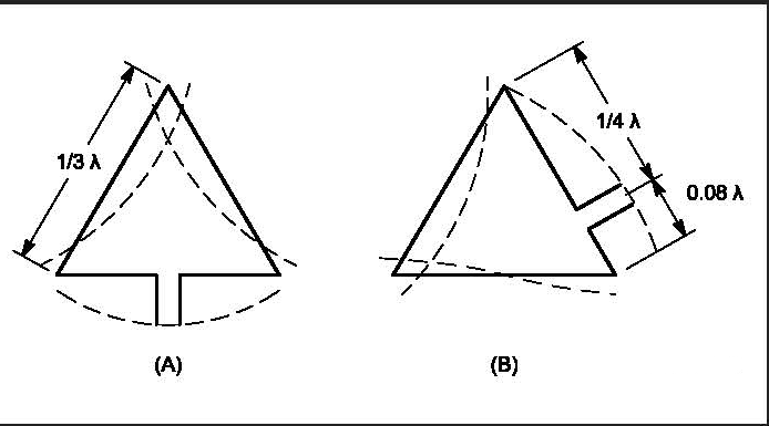
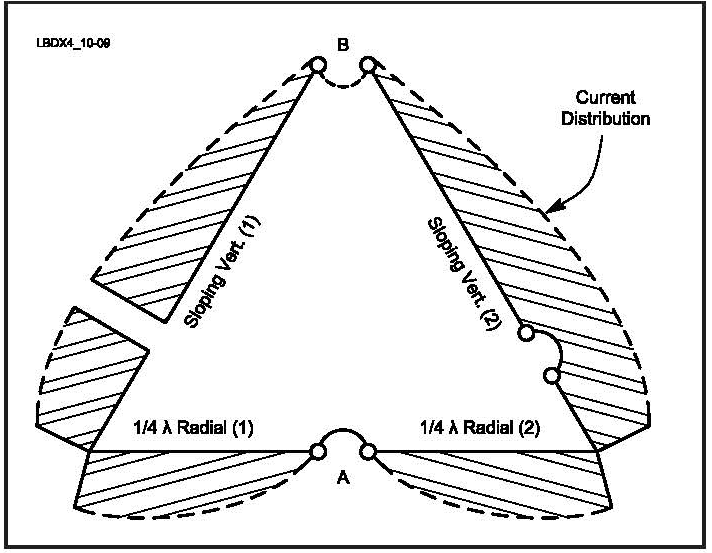
. Note that all the work shown here can be scaled to 5 MHz 60 meters or 7 MHz 40 meters for NVIS. Omnidirectional radiation patterns are produced by the simplest practical antennas monopole and dipole antennas consisting of one or two straight rod conductors on a common axisAntenna gain G is defined as antenna efficiency e multiplied by antenna directivity D which is expressed mathematically as. The loop can be arranged as square quad or diamond equilateral triangle with apex up or down feedpoint on the bottom side and corner.
Note that the vertical pattern of a dipole changes radically as height is changed above 14 wavelength or 125 feet on 160 meters or 65 feet on 80 meters. Each variation changes the characteristics slightly regarding the impedance gain polarization pattern and from the DX point of view the take-off angles.

Delta Loop Antenna Radiation Patterns Hy Power Antenna Company

Radiation Pattern Of The Loop Antenna Download Scientific Diagram

Delta Loop Antenna Radiation Patterns Hy Power Antenna Company

Delta Loop Antenna Radiation Patterns Hy Power Antenna Company

Delta Loop Antenna Radiation Patterns Hy Power Antenna Company
All Band Use Of Vertical Plane Deltas
Top Band Hams Vertical Loop Antennas
Delta Loop
0 comments
Post a Comment